


 5 / 7
5 / 7

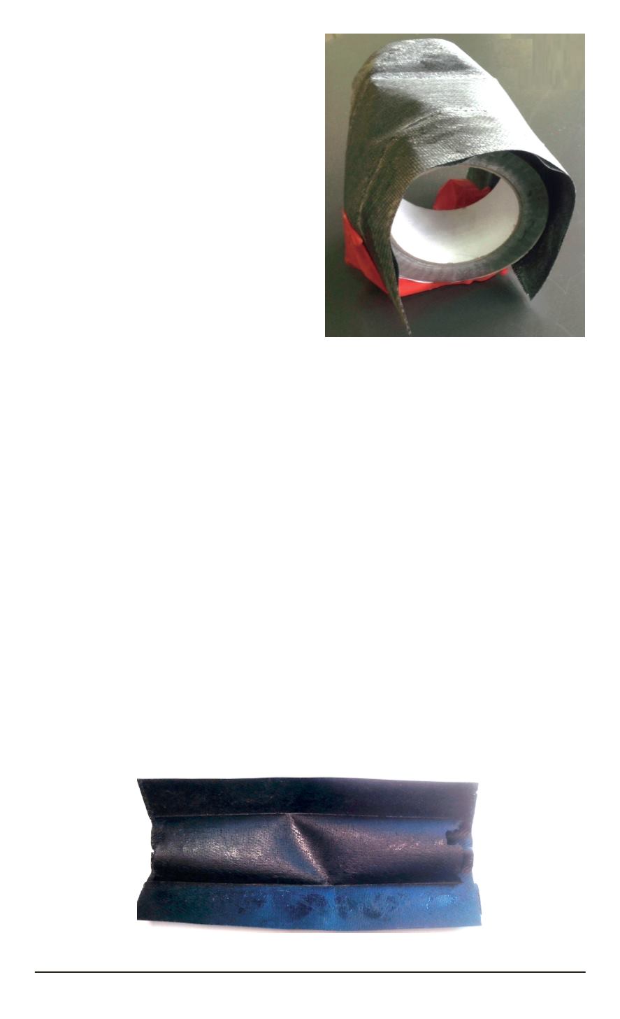
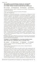
Fig. 4. Folded short test sample
long test specimen, loaded with
concentrated force in its geometrical
center, changed its form from initial
stable to deformed, self-locked one,
as shown in Fig. 5.
3.
Analysis.
Stowage and
deployment analysis of the proposed
design was fulfilled with using
LS-DYNA nonlinear code. The
triangle unit with proposed bi-stable
composite beams components was
analyzed as a typical building block
of real space trusses. The specimen
observed is shown in Fig. 2.
Numerical analysis of unit was
separated into two stages. First was
stowage analysis, when the final form
of the truss was deformed with concentrated forces to the folded state with
the accumulation of potential energy. Second stage was the deployment
analysis, when the folded truss was deployed to final state by releasing the
potential energy.
During the first stage of the analysis, the specimen was constrained by
restricting out-of-plane translational motion in the corners of the structure.
Concentrated tension forces were applied at geometrical centers of the
beams to flatten its cross-sections. Folding of the beams was then caused
by the concentrated forces, applied at the same points, but directed normally
to final state of the truss.
The second stage of the analysis began with the fixing the model in
stowed state and damping its oscillations, caused by the sudden application
of constrain. The deployment analysis was then started, when the most
of the kinetic energy of the specimen was dissipated and the constrains
were released. There were no constrains at the time of deployment applied.
4-noded shell finite elements were used for numerical modelling on both
stages of the analysis. Material properties used are listed in Table.
Fig. 5. Long test specimen in self-locked state
ISSN 0236-3941. Вестник МГТУ им. Н.Э. Баумана. Сер. “Машиностроение” 2015. № 1 53