


 2 / 12

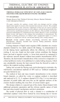
Fig. 1. Coplanar channel:
a
— is a channel general arrangement;
b
— is a channel-developed view
forces in the interfin channels on the opposite sides of the circuit. Oppositely
directed cross-vortex flows interact through the mixing layer.
In the layer of cross flows mixing, continuous deformation and
transformation of the interacting flows boundary layers occur that determine
the complex pattern of their interaction mechanisms accompanied by an
impulse, heat, and mass transfer.
The heat transfer intensification in this channel is determined by
a combination of several interaction mechanisms, such as a generation of
turbulent pulses in the mixing layer and their transfer by a vortex flow
onto the exposed surface of the interfin channels; a substitution of hot
layers of a heat agent near the heat-release surfaces with colder layers of
the opposite periphery flows.
The experimental analysis of CC thermal hydraulic characteristics
(THC) was conducted under the following conditions. The fins angles
were both symmetrical and nonsymmetrical within the range of the total
angle
2
β
= 45
. . .
120
◦
, the fins height on the heat-release surface
h
1
constituted a half of the channel height
h
. The profile of the interfin
channels characterized by the fin height to the channel width ratio
χ
=
h
1
/a
was symmetrical and asymmetrical in the range of
χ
= 0
.
25
. . .
1
.
1
, and the
range of the relative fin pitch ratio
ˉ
t
=
t/δ
f
on the heat removing surface
constituted 2.36. . . 7.00, the range of flow modes was Re
= 10
3
. . .
6
∙
10
4
.
There was a low fin density across the tops, which resulted in heat transfer
into the adjacent fins approaching zero.
ISSN 0236-3941. HERALD of the BMSTU. Series Mechanical Engineering. 2015. No. 2 45